画笔
一、构造函数画笔有两个构造函数,分别看下:
Pen( const Color& color, REAL width);
Pen( const Brush* brush, REAL width);
注意:第一个构造函数:从一个颜色构造一个单色画笔,平时用的比较多
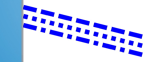
第二个构造函数要特别注意,它可以从一个画刷构造一个画笔,当画刷是纯色时,构造的也是纯色画笔,这与第一个构造函数效果相同,但画刷并不一定都是纯色的,如果是纹理画刷的话,构造出来的画笔会是什么样呢,我们看看
例子:(同样用力宏哥哥的照片)
Image image(L"img.bmp");
TextureBrush tBrush(&image);
Pen pen(&tBrush,40);
//在三个不同区域画椭圆,看实现效果
//试探在同一张图中画椭圆会怎样
graphics.DrawEllipse(&pen,100,20,200,100);
graphics.DrawEllipse(&pen,20,150,200,100);
//试探超出会怎样
graphics.DrawEllipse(&pen,400,20,200,100);//水平超出
graphics.DrawEllipse(&pen,20,450,200,100);//垂直超出
王力宏的照片:


从运行结果上可以看出,背景图会在绘制区域横向和纵向平铺,然后根据画笔的位置,将其显示!
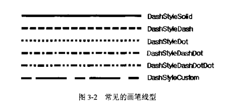
二、设置画笔样式-----Pen::SetDashStyle(dashStyle)
DashStyle定义了下面几种线型:
enum DashStyle{
  DashStyleSolid = 0,   //实线
  DashStyleDash = 1,  //虚线
  DashStyleDot = 2, //点线
  DashStyleDashDot = 3, //点划线
  DashStyleDashDotDot = 4, //双点划线
  DashStyleCustom = 5 //自定义线型
};
示例:
Pen pen(Color(255, 0, 0, 255), 15);
pen.SetDashStyle(DashStyleDash);//虚线
graphics.DrawLine(&pen, 0, 50, 400, 150);
pen.SetDashStyle(DashStyleDot);//点线
graphics.DrawLine(&pen, 0, 80, 400, 180);
pen.SetDashStyle(DashStyleDashDot);//点划线
graphics.DrawLine(&pen, 0, 110, 400, 210);
Pen类的成员函数SetDashPattern(设置线型风格)可以使用一个预定义的数组来描述画笔的虚实,这个数组的格式为:
[画线部分长度,间隔部分长度,画线部分长度,间隔部分长度……]
数组的大小由开发者自定义,画笔会按照自定义的格式循环画线例子:
//定义线型数组
REAL dashVals[4] = {
 5.0f, //线长5个像素
 2.0f, //间隔2个像素
 15.0f, //线长15个像素
 4.0f}; //间隔4个像素
 Pen pen(Color(255, 0, 0, 0), 5);
 //设置线型
 pen.SetDashPattern(dashVals, 4);
 graphics.DrawLine(&pen, 5, 20, 405, 200);

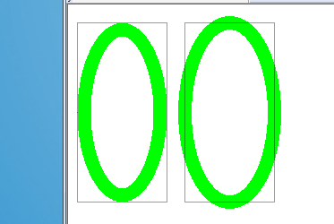
penAlignment枚举了两种对齐方式:
enum PenAlignment{
 PenAlignmentCenter = 0,//居中对齐,默认
 PenAlignmentInset = 1,//嵌入方式
}; 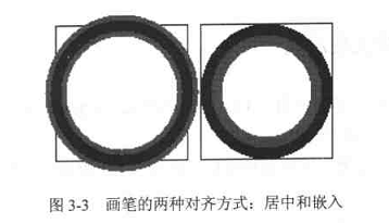
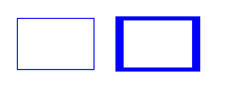
例子:
Pen greenPen(Color(255, 0, 255, 0), 15);
Pen BorderPen(Color(100,0,0,0),1);//透明度设为100
// 设置成嵌入式
greenPen.SetAlignment(PenAlignmentInset);
graphics.DrawEllipse(&greenPen, 10,20, 100, 200);
graphics.DrawRectangle(&BorderPen,10,20,100,200);
//设置成居中
greenPen.SetAlignment(PenAlignmentCenter );
graphics.DrawEllipse(&greenPen, 130, 20, 100, 200);
graphics.DrawRectangle(&BorderPen,130,20,100,200);
五、画笔的缩放与旋转(待完)
注意,这是对画笔的缩放与旋转,在画笔缩放或旋转后,用这个画笔画的图像都是缩放/旋转的,这里并不是对图像缩放/旋转,这点一定要清楚。
缩放
几个缩放函数:
Pen::ScaleTransform(sx, sy, order)//方法一,sx指定水平缩放倍数,sy指定纵向缩放倍数
Pen::SetTransform(matrix)//方法二,
Pen::MultiplyTransform(matrix, order)//方法三,
Pen::ResetTransform() //重置缩放参数,即把缩放参数全部去掉,还原到原来的1:1状态
后面两个函数还不会用,方法一比较简单,举个例子吧:
//缩放一-----ScaleTransform
//放大之前画个图,放大之后再画个图,对比一下
Pen pen(Color(255, 0, 0, 255), 2);
graphics.DrawRectangle(&pen, 50, 50, 150, 100);
// 水平放大8倍,垂直放大4倍
pen.ScaleTransform(8, 4);
graphics.DrawRectangle(&pen, 250, 50, 150, 100);
关于重置Pen::ResetTransform(),贴段代码吧
Pen pen(Color(255, 0, 0, 255), 2);
// 水平放大8倍,垂直放大4倍
pen.ScaleTransform(8, 4);
graphics.DrawRectangle(&pen, 250, 50, 150, 100);
pen.ResetTransform();
graphics.DrawRectangle(&pen, 450, 50, 150, 100);

旋转函数:
Pen::RotateTransform(angle, order)//第一个参数表示旋转度数,第二个参数表示往左旋转还是往右旋转例子:
//画笔要旋转,粗细要大于1,否则应用旋转函数不会成功
Pen pen(Color::Green,5);
pen.ScaleTransform(1,6);
graphics.DrawEllipse(&pen,20,20,100,100);
//往右旋转60度
pen.RotateTransform(60,MatrixOrderAppend );
graphics.DrawEllipse(&pen,150,20,100,100);
//再往右旋转60度,也就是相对于原来的旋转了120度
pen.RotateTransform(60,MatrixOrderAppend );
graphics.DrawEllipse(&pen,300,20,100,100);
//注意:RotateTransform按说设置成MatrixOrderPrepend会往左旋转,但我设置成它之后,总是不成功的,不知为什么

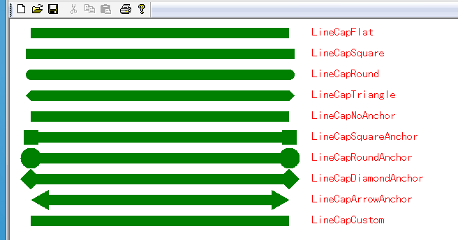
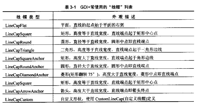
“线帽”,顾名思义,就是线条首尾的外观,默认情况下,使用画笔绘制的直线,其起点和结束点的外观都是相同的——方形。在程序设计中,我们可以对这两个端点的外观进行修改。对于起点,可以使用SetStartCap,对于终点,可以使用SetEndCap来完成。
看这两个函数:
Pen::SetStartCap(startCap)//设置起点线帽 Pen::SetEndCap(endCap)//设置终点线帽线帽是由LineCap枚举列出的。LineCap定义如下:
enum LineCap{
 LineCapFlat = 0,
 LineCapSquare = 1,
 LineCapRound = 2,
 LineCapTriangle = 3,
 LineCapNoAnchor = 0x10,
 LineCapSquareAnchor = 0x11,
 LineCapRoundAnchor = 0x12,
 LineCapDiamondAnchor = 0x13,
 LineCapArrowAnchor = 0x14,
 LineCapCustom = 0xff
};
对于它们各是什么线帽,看例子:(对于每一种线帽都一一把它画了出来,并在其后标上该线帽的名字,大家可以比对一下) Pen pen(Color::Green,15); SolidBrush brush(Color(255,255,0,0)); FontFamily fontfamily(L"黑体"); Font font(&fontfamily,16,FontStyleRegular,UnitPixel); pen.SetStartCap(LineCapFlat); pen.SetEndCap(LineCapFlat); graphics.DrawLine(&pen,PointF(30,20),PointF(400,20)); graphics.DrawString(L"LineCapFlat",-1,&font,PointF(430,10),&brush); pen.SetStartCap(LineCapSquare); pen.SetEndCap(LineCapSquare); graphics.DrawLine(&pen,PointF(30,50),PointF(400,50)); graphics.DrawString(L"LineCapSquare",-1,&font,PointF(430,40),&brush); pen.SetStartCap(LineCapRound); pen.SetEndCap(LineCapRound); graphics.DrawLine(&pen,PointF(30,80),PointF(400,80)); graphics.DrawString(L"LineCapRound",-1,&font,PointF(430,70),&brush); pen.SetStartCap(LineCapTriangle); pen.SetEndCap(LineCapTriangle); graphics.DrawLine(&pen,PointF(30,110),PointF(400,110)); graphics.DrawString(L"LineCapTriangle",-1,&font,PointF(430,100),&brush); pen.SetStartCap(LineCapNoAnchor); pen.SetEndCap(LineCapNoAnchor); graphics.DrawLine(&pen,PointF(30,140),PointF(400,140)); graphics.DrawString(L"LineCapNoAnchor",-1,&font,PointF(430,130),&brush); pen.SetStartCap(LineCapSquareAnchor); pen.SetEndCap(LineCapSquareAnchor); graphics.DrawLine(&pen,PointF(30,170),PointF(400,170)); graphics.DrawString(L"LineCapSquareAnchor",-1,&font,PointF(430,160),&brush); pen.SetStartCap(LineCapRoundAnchor); pen.SetEndCap(LineCapRoundAnchor); graphics.DrawLine(&pen,PointF(30,200),PointF(400,200)); graphics.DrawString(L"LineCapRoundAnchor",-1,&font,PointF(430,190),&brush); pen.SetStartCap(LineCapDiamondAnchor); pen.SetEndCap(LineCapDiamondAnchor); graphics.DrawLine(&pen,PointF(30,230),PointF(400,230)); graphics.DrawString(L"LineCapDiamondAnchor",-1,&font,PointF(430,220),&brush); pen.SetStartCap(LineCapArrowAnchor); pen.SetEndCap(LineCapArrowAnchor); graphics.DrawLine(&pen,PointF(30,260),PointF(400,260)); graphics.DrawString(L"LineCapArrowAnchor",-1,&font,PointF(430,250),&brush); pen.SetStartCap(LineCapCustom); pen.SetEndCap(LineCapCustom); graphics.DrawLine(&pen,PointF(30,290),PointF(400,290)); graphics.DrawString(L"LineCapCustom",-1,&font,PointF(430,280),&brush);
七、自定义线帽
GDI+使用CustomLineCap类来自定义线帽,该类的构造函数为:
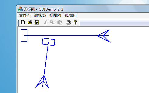
CustomLineCap( const GraphicsPath* fillPath, const GraphicsPath* strokePath, LineCap baseCap, REAL baseInset);在上述的构造函数中,我们可以从一个路径创建自定义的线帽。使用SetCustomStartCap和SetCustomEndCap将由CustomLineCap函数创建的自定义的线帽与画笔相关联。 示例:
//自定义线帽
GraphicsPath StartPath,EndPath;
//构造开始点线帽路径:矩形
StartPath.AddRectangle(Rect(-10,-5,20,10));
//构造结束点线帽路径:箭头
EndPath.AddLine(0,-20,10,0);
EndPath.AddLine(0,-20,-10,0);
EndPath.AddLine(0,-10,10,0);
EndPath.AddLine(0,-10,-10,0);
Pen pen(Color(255,0,0,255),2);
CustomLineCap startCap(NULL,&StartPath);
CustomLineCap endCap(NULL,&EndPath);
//将线帽与画笔相关联
pen.SetCustomStartCap(&startCap);
pen.SetCustomEndCap(&endCap);
//先画条试验线
graphics.DrawLine(&pen,20,30,300,30);//水平的
graphics.DrawLine(&pen,100,50,80,200);//斜的
直线连接点是两条端点重合或重叠的直线形成的公共区域。GDI+提供了四种直线连接方式:斜接(LineJoinMiter)、斜切(LineJoinBevel)、圆形(LineJoinRound)、剪裁斜接(LineJoinMiterClipped)。
LineJoin枚举了常见的连接方式,其定义是:
enum LineJoin{
 LineJoinMiter = 0, //斜接
 LineJoinBevel = 1, //斜切
 LineJoinRound = 2, //圆形
 LineJoinMiterClipped =3 //剪裁
};
看一下连接点示例吧:(先看距形中的应用,再看再条直线连接时的转角) //为了强化效果,特地把直线设的特别粗
Pen pen(Color::Green,25);
FontFamily fontfamily(L"宋体");
Font font(&fontfamily,18,FontStyleRegular,UnitPixel);
SolidBrush brush(Color(255,255,0,0));
//先看看矩形的边效果
pen.SetLineJoin(LineJoinMiter);//设定为斜接
graphics.DrawRectangle(&pen,20,20,150,100);
pen.SetLineJoin(LineJoinBevel);//设定为斜切
graphics.DrawRectangle(&pen,220,20,150,100);
pen.SetLineJoin(LineJoinRound );//设定连接方式为圆形
graphics.DrawRectangle(&pen,420,20,150,100);
pen.SetLineJoin(LineJoinMiterClipped);//设定为剪裁斜接
graphics.DrawRectangle(&pen,620,20,150,100);
//再看直线的连接效果
PointF points[]={PointF(20,220),PointF(100,200),PointF(50,280)};
graphics.SetSmoothingMode(SmoothingModeHighQuality);//设定连接时的平滑度
pen.SetLineJoin(LineJoinMiter);//设定为斜接
graphics.DrawLines(&pen,points,3);
points[0].X+=100;points[1].X+=100;points[2].X+=100;
pen.SetLineJoin(LineJoinBevel);//设定为斜切
graphics.DrawLines(&pen,points,3);
points[0].X+=100;points[1].X+=100;points[2].X+=100;
pen.SetLineJoin(LineJoinRound );//设定连接方式为圆形
graphics.DrawLines(&pen,points,3);
points[0].X+=100;points[1].X+=100;points[2].X+=100;
pen.SetLineJoin(LineJoinMiterClipped);//设定为剪裁斜接
graphics.DrawLines(&pen,points,3); 运行结果: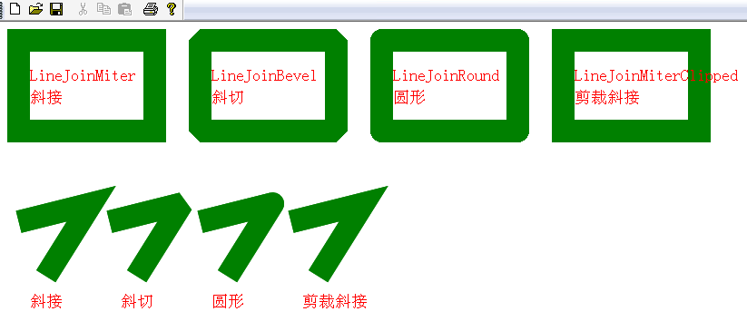
画笔的斜连接限制(交集长度限制)---SetMiterLimit
当两条直线以一定的角度相交时,其形成的交集如图所示:
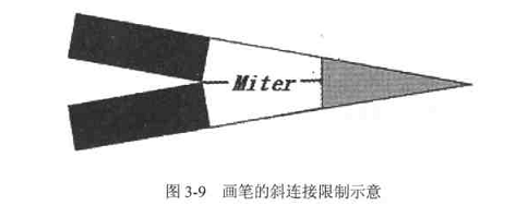
在实际绘制中,Miter后的灰色部分是不会绘制的,也就是说,会少个角,为什么会这样呢,考虑一种情况,当两条直线之间的夹角较小或者更极端一点,以近乎平行的方式相交,使用LineJoinMiter方式绘制这两条的交集时,其结果则令人难以想像,因为细窄的交集快成了一条直线,接近无限的延伸下去,为了解决这个问题,当两条直线直交时,我们就需要对它们的交集的长度进行裁剪,超出部分将不会被绘制,而这个交集的长度就是由画笔的斜连接限制来确定的。
画笔的斜连接限制是指斜连接长度与画笔宽度之间所允许的最大比值。默认值是10。大家可以通过SetMiterLimit函数来设置画笔的斜连接限制值。
示例1(采取默认值):
PointF points[]={PointF(20,220),PointF(500,220),PointF(30,280)};
pen.SetLineJoin(LineJoinMiter);//设定为斜接
graphics.DrawLines(&pen,points,3); 
PointF points[]={PointF(20,220),PointF(500,220),PointF(30,280)};
pen.SetLineJoin(LineJoinMiter);//设定为斜接
pen.SetMiterLimit(2.0f);
graphics.DrawLines(&pen,points,3); 
收藏的用户(0) X
正在加载信息~
推荐阅读
最新回复 (0)
站点信息
- 文章2312
- 用户1336
- 访客11618800
每日一句
Books are passports you never need to renew.
书籍是永不过期的护照。
书籍是永不过期的护照。
 You Only Look Once:Unified, Real-Time Object Detection-CVPR-2016
 Thinkpad x1 Extreme黑苹果10.14.5安装完成
 C++ 11新语法获取系统盘符
 cocos2d-x横版ARPG过关游戏
 程序员应该使用Linux的7个理由
 去除WPS2016个人版自带广告弹窗
 x86 emulation currently requires hardware acceleration
- 数字证书及CA的通俗介绍
 Android c++屏幕实时录制
 快速入门-如何在Java上使用Redis
 请启用虚拟机平台 windows 功能并确保在 bios 中启用虚拟化
 diskgenius 保存分区表时出现错误 代码00000032方法解决
 .a静态库创建与合并
新会员